3D modelling can be fun for making purely virtual models of things. With the advent of 3D printing, however, you can now model things that don’t exist yet, and get them delivered to your home for modest fee (or even printing it yourself, if you happen to own a 3D printer).
However, 3D CAD tools are often complicated, expensive or both. I’ve found and grown to like Solvespace. It’s a parametric CAD program that looks like old DOS software. But a) that’s the way I like it and b) it’s pretty well documented. I wouldn’t want to model a car with this, but for simple geometric shapes, it’s perfectly serviceable.
In this tutorial, we will be making an aid for keeping the angle while sharpening knives. It’s a simple shape, so it lends itself well to our subject.
Installation
Solvespace is packaged for most Linux distributions. While the last “official” version was released almost exactly a year ago as of the time of this post (April 2021), I haven’t found any missing features for the simple geometry I will be using. Just install Solvespace via the package manager of your choice, or, if on Windows, download and install from the Downloads page.
If you’d rather read a better tutorial that’s a bit more involved, read this instead.
The Thing
Here’s the thing:
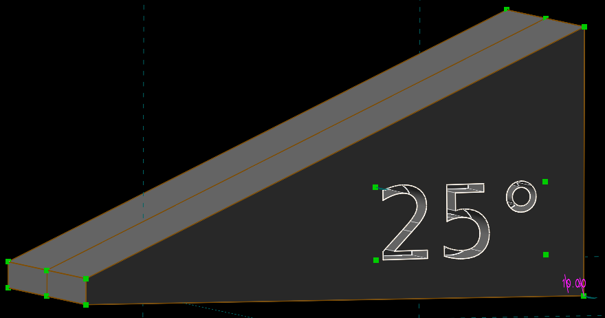
The thing we’re making.
Basically, it’s a wedge that’s slightly truncated at the front. I will be using it for helping me keep the blade angle constant while sharpening my knives. It’s not meant to go on the stone itself, only to periodically recalibrate my hand position. I’ve gotten the idea after using one of these thingies that clip to the back of the blade, and getting a blade angle that was way too small. This should work better, and I’ve long wanted to make 3D printing work for me.
Getting started
Welp, start Solvespace. You’ll see something like this:
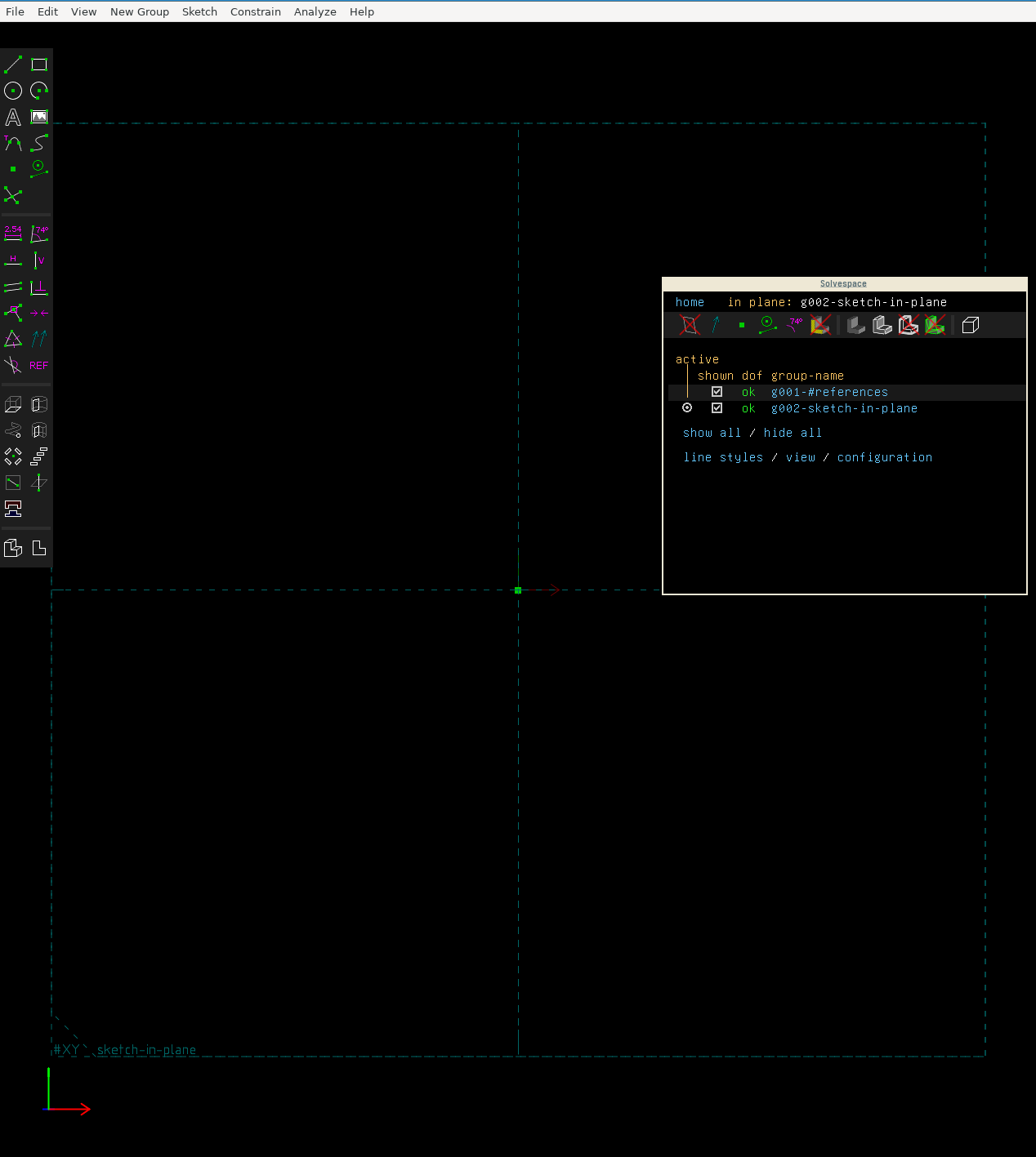
The solvespace interface after starting the program
The toolbar at the top is almost self-explanatory. Use it to save or open other files, change some options, read the help, whatever. Some of the menus are more interesting than others, but we’ll get to those in time.
Direct your attention to the toolbar on the left. The top third of the toolbar contains buttons to add new elements to the drawing. Then, we get a multitude of buttons to add constraints to these elements. Finally, there’s some “New groups” buttons that we’ll discuss later.
The major part of the interface is taken up by the main view. It’s here where you’ll be drawing and modifying elemens that will make up the complete object.
You can shift the view by dragging with the right mouse button, or rotate it by dragging with the middle button. You can reset your view with w. The left allows you to select things, via clicking or multiple elements via dragging.
Finally, don’t underestimate the floating window. It shows a list of all your groups, which is an important concept in Solvespace. Additionally, it will show you extra information on what you’ve selected with your mouse (left button) and alert you to any conflicting constraints you’ve defined. You will always want to have this window available.
But enough of the preliminaries, let’s get started.
Sketchy sketchy
Solvespace works based on groups. It’s what’s shown in the floating window, and what 3D objects are made out of. We’ll see that in a moment. For now, let’s start sketching. Select the line tool (top left sidebar button), and draw some lines.
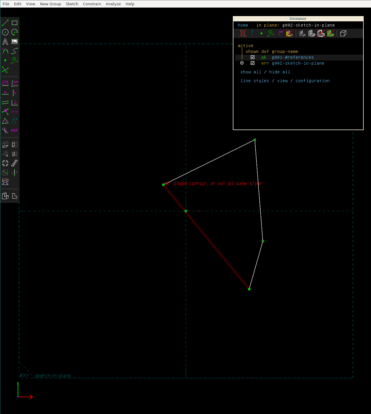
Just draw some lines with the line tool
You’ll see something like the above. Solvespace complains that the contour you’ve drawn is not closed, and is thus useless for making 3D objects. Additionally, the floating window now shows an error for the active group you’re editing in the “dof” (degrees of freedom) column. This tells you something’s not OK. Let’s make a wedge instead.
Delete the existing lines with Ctrl+A (Edit → Select All) and Delete (Edit → Delete), and draw a wedge, starting at the green point in the middle of the screen. You’ll see some slight snapping. Additionally, observe the purple ‘H’ and ‘V’s that show up when your line is close to horizontal or vertical. All of those are constraints that Solvespace will create when you click the left mouse button to select a place for the final point of the line.
Now make that wedge, we’ll go over the results.
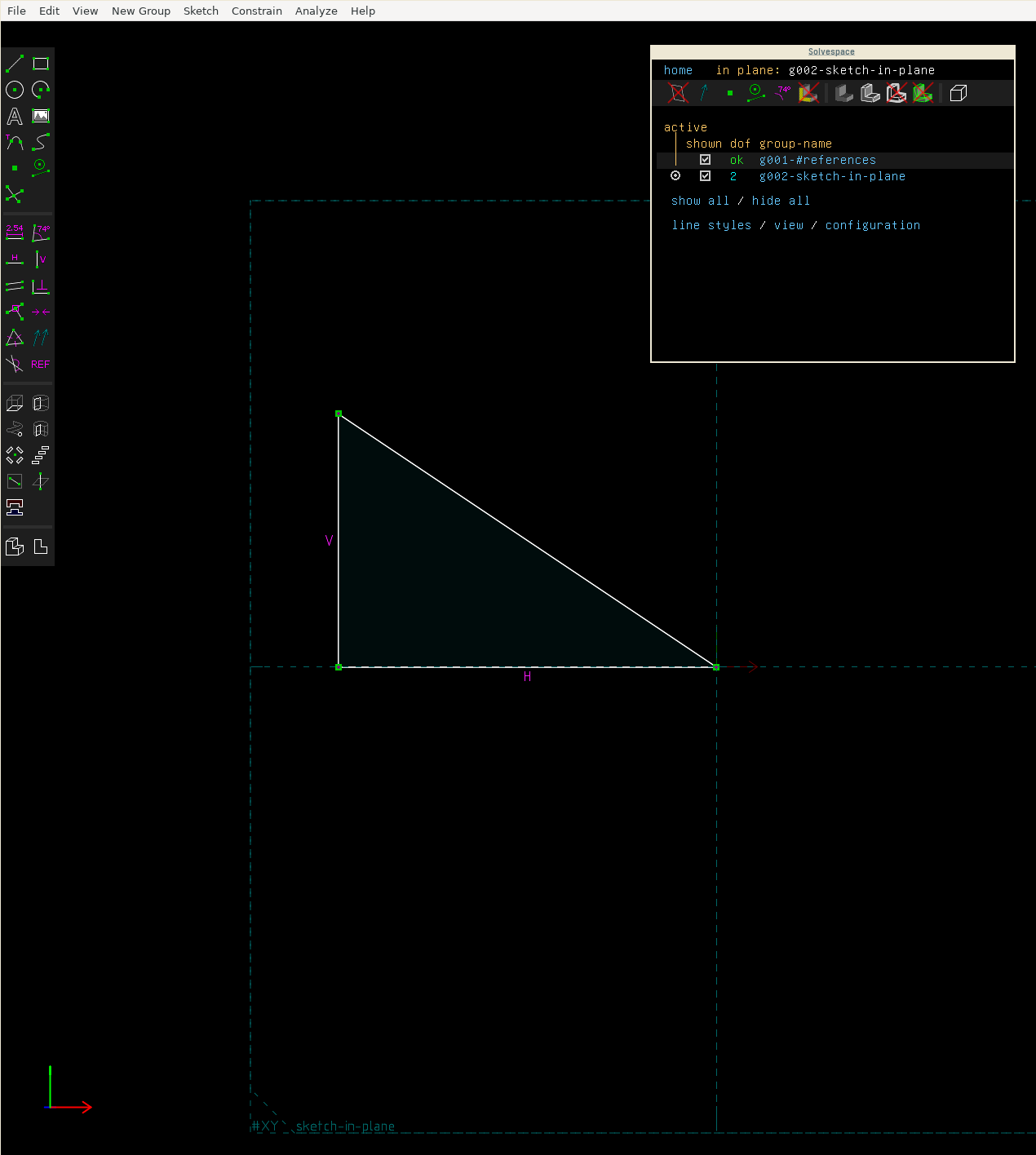
The wedge we’ve created
This is a beautiful wedge, isn’t it? As alluded to before, Solvespace has added some constraints for us already when it thought they were useful. Purple ‘H’ and ‘V’s are horizontal and vertical constraints. They mean that the line they’re applied to must be horizontal or vertical. You can delete the constraint by clicking the letter and pressing Delete. You can also add constraints by selecting a line and clicking the second row of buttons in the “constraint” section of the sidebar, or pressing H or V.
Solvespace has also added three other constraints that are less apparent: The squares with the dots in them mark “lies on” constraints. Because you were using the multiline tool, Solvespace constrained the end point of the previous line to the beginning of the next line. You can add those constraints manually by selecting two points and clicking the “lies on” constraint button (4th line left of the “constraint” sidebar section) or pressing O.
You can get additional information about constraints in the floating window. Select a constraint (by clicking a “H”), and it will show you what it is the constraint constrains. You can get to the “lies on” constraints by selecting a line endpoint, and then clicking the constrained in the “Constrained By” section in the floating window.
You’ve now constructed a triangle with some constraints. However, stuff can still move around. Try dragging one of the points or lines to see this. The “dof” column in the floating window shows how “mobile” your design is. Try adding a distance constraint (D) to one of the sides of the triangle to decrease the degrees of freedom. You’ve reduced the degree of freedom of your sketch, and now you’re only able to drag points into positions where all constraints are still satisfied.
So far so good. Let’s make the shape more complicated, and see what happens when you define constraints that “Solve"space can’t solve.
When constraints collide
Turns out that you actually have to put in some work to generate conflicting constraints. When adding constraints to a triangle, Solvespace can actually know that the constraint you’re adding is useless, and automatically transforms it into a reference measurement with a “REF” suffix. On rectangles, this doesn’t work as well, so I’ve constructed a conflict for you.
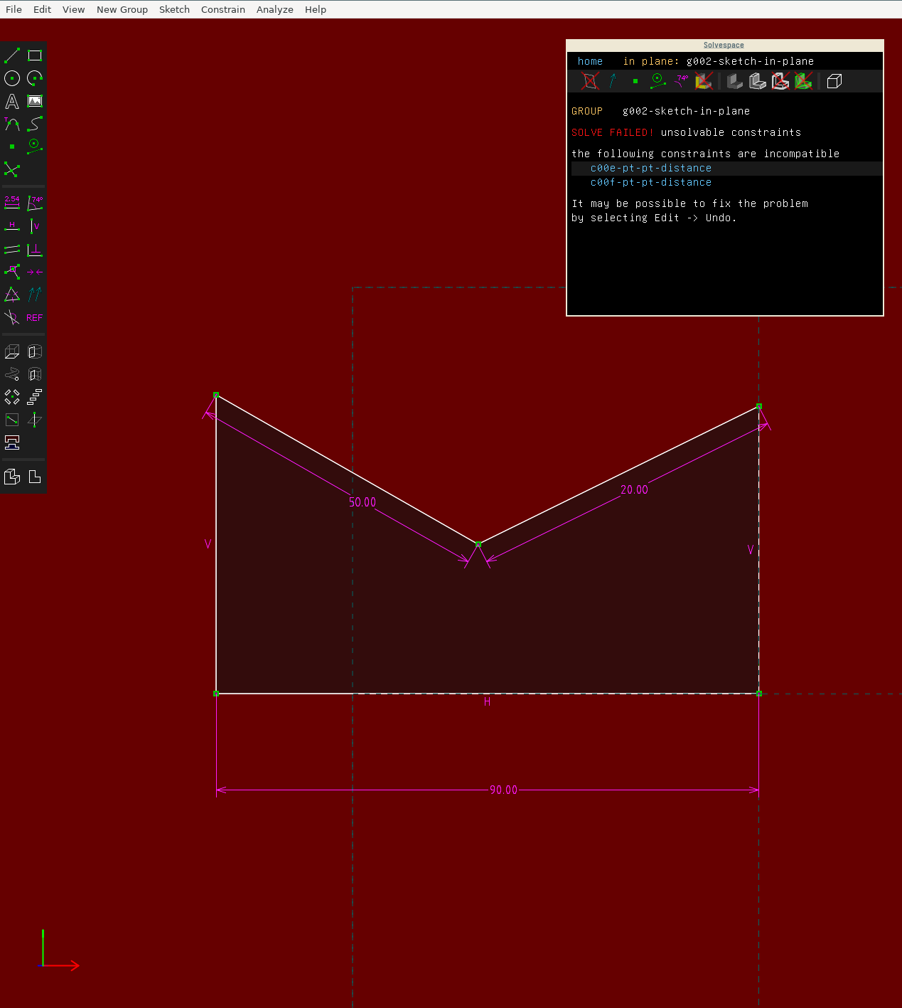
A conflict shown in Solvespace
Note the red background and the message in the floating window. The floating window also shows you which constraints are in conflict, and you can click to select constraints and delete them.
The Thing II: Cut it off
I don’t know if you could tell from the initial picture, but the sharpening guide is truncated at the front. It’s actually more of a trapezoid. I’ve designed it this way so the knife is easier to align to the guide, and the tip does not extend all the way below the knife. The sketch for the basic shape should look like this, with all constraints added: Some length constraints to make the size correct, horizontal and vertical constraints, and an angle constraint to make the guide the correct angle (110° for a 20-degree sharpening angle).
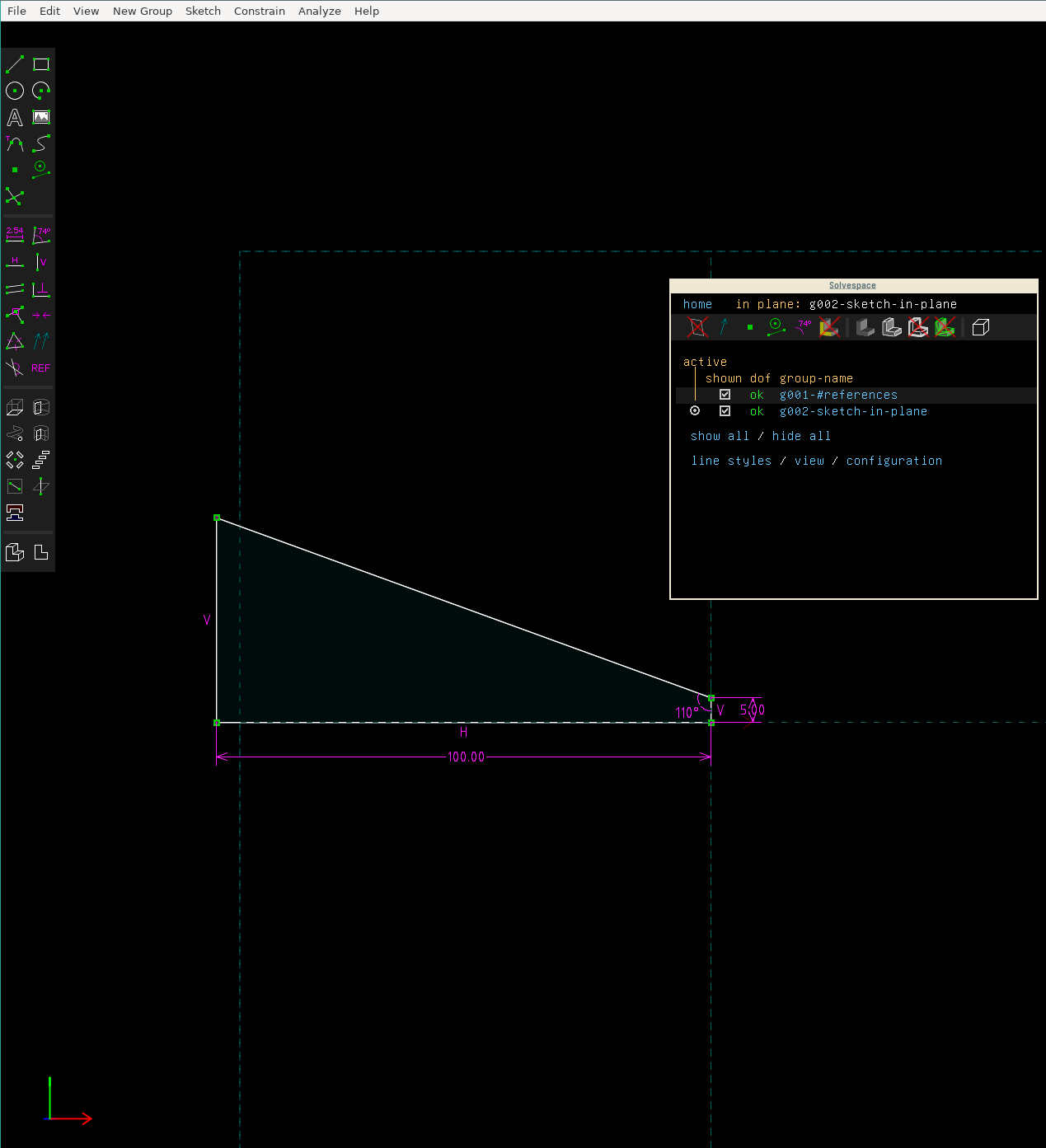
The basic shape of the guide
As you can see in the floating window, the “dof” column shows “OK”. This means that the design is fully constraint, and the position of all points is fixed.
We can now go and make it 3D.
Entering the third dimension
After sketching, you can apply operations to a 2D sketch to make it 3D. In our example, we will extrude. This basically means moving the shape in one dimension. The resulting shape is the full volume covered during this move. I hope it’s clearer when you’re doing it in Solvespace. Click New Group → Extrude, the top button in the bottom group of the sidebar, or press Shift+X to extrude.
To make it easier to understand, set the “extrude plane sketch” to “both sides”. You can now click “home” in the floating window to return. Rotate around a bit and witness the glorious three-dimensional object you’ve just created (reset your view with W). Also note that you now have a new group in your group list. You can switch between editing the extruded object and the original sketch by using the “active” radiobutton in the group list. Try it. You can also update parameters of your sketch, and the extruded group will automatically change shape to reflect these changes. That’s the magic of parametricity.
Also note that the extrusion has a DOF of 1. This is because we haven’t specified the width of our guide. Select a line that was created with the extrusion and add a distance constraint (D). Now you’ve fully constrained the object, and the DOF column shows “OK”.
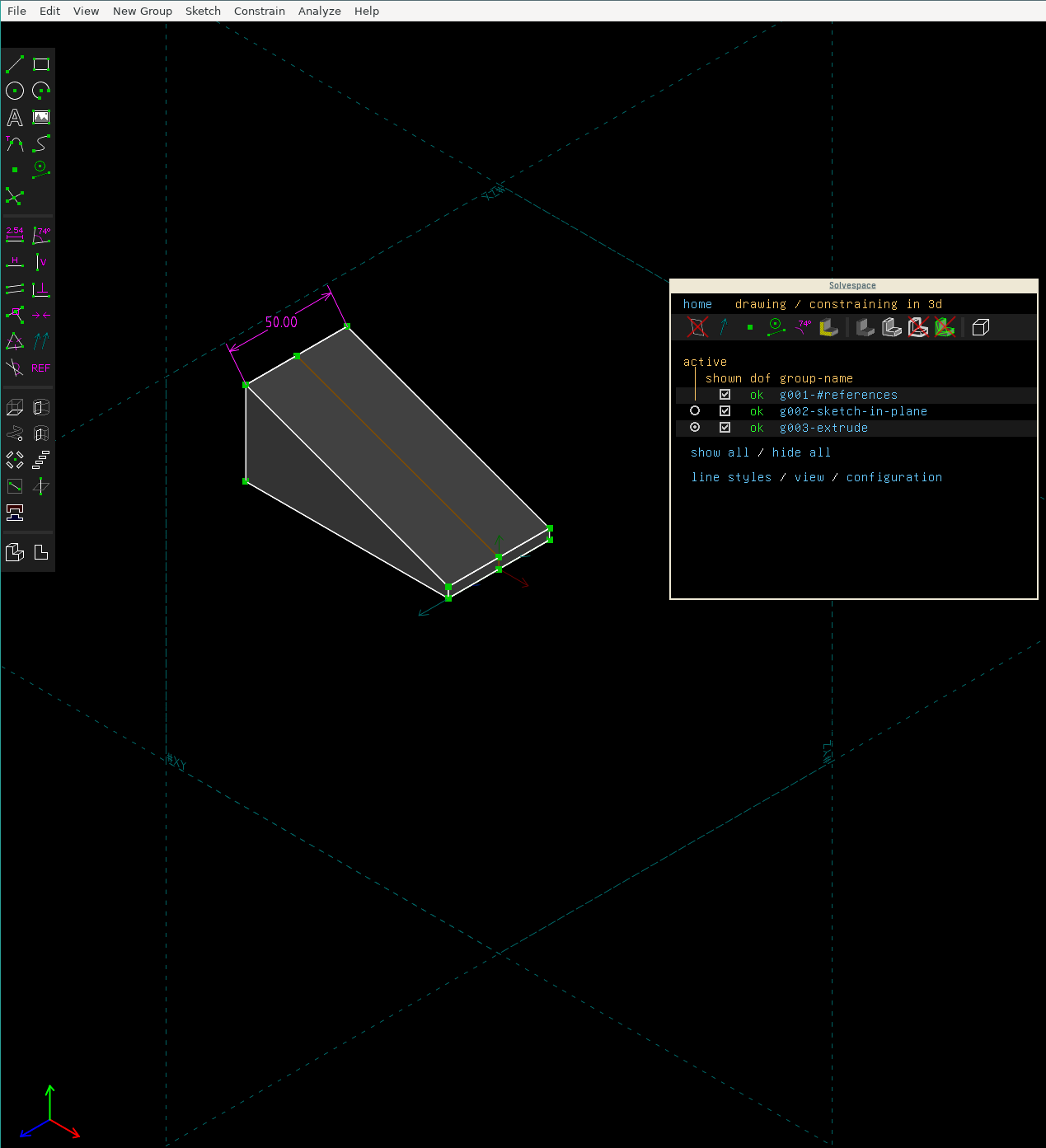
The fully constrained 3D object
We’re almost done, but I want to differentiate between the different guides with an inset text showing the blade angle. I’ve made three guides, with an angle of 17°, 20° and 25° respectively, and it would be nice to be able to tell them apart. Insetting some text will also give you an idea of how to make more complex shapes.
Final touches
For adding the text, we need a new sketch. We created our first sketch for the base shape in the default workplane, the XY axis. You can see this by activating the group in the floating window. You’ll see “#XY sketch in plane” in the bottom left corner. For the inset text, we now want to sketch on the side of the extruded object.
To do this, we want to create a new sketch in a new workplane, with the workplane being the side of our extruded wedge. We can do this by selecting the bottom and right edge of the wedge and the point between them and pressing Shift+W. This will create a new workplane on the surface of our object. We can now add text via the text tool by clicking and dragging. Change the text via the “change” button in the floating window. You can also add constraints to specify the location of the text in more detail (I’ve done this here, but it’s not necessary).
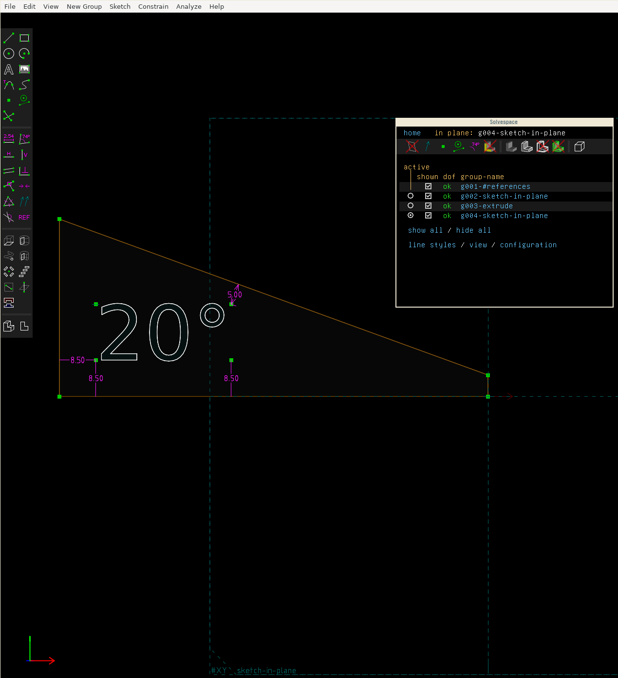
The text on the side of our wedge
Finally, we extrude again using X. This time, we want the extrusion one-sided, and we want to calculate the difference of the extrusion for an inset text. Add a distance constraint to specify the depth of the extrusion (I used 10mm). If you have difficulty selecting the extrusion for a constraint, you can go back to the group view via “home” and change the opacity of the first extrusion by selecting it in the group list and editing the “opacity” value.
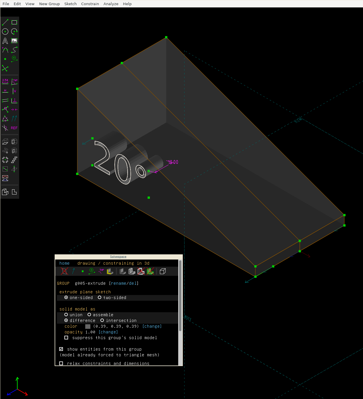
The final product, with inset text
And we’re done!
What do do now
Make sure that the export scale factor is set to 1:1 in the Solvespace configuration (Floating window → configuration) and export an STL file via File → Export triangle mesh. You can now send this to a 3D printing provider of your choice, or print it yourself if you happen to own a 3D printer.